


My three most recent builds were using ASRock Rack server boards. The two boards X470D4U and the ROMED8-2T use the TPM2-S/INFINEON module.
The one that is different is the X570D4I-2T which uses the TPM2-SLI module. I looked around and couldn't find a place to buy the TPM2-SLI module, so I decided to make my own. Since I was making one, I figured I would make the modules for the other boards too even though they were available for purchase.
I run Windows 11 on the X470D4U and ESXi on the other two. ESXi does not support the fTPM implementation for host attestation, hence the need for a hardware TPM module instead.
This proved to be beneficial for me on the X470D4U for two reasons:
- The latest bios available contains the AMD AGESA of 1.2.0.0 which has the stuttering issue when the fTPM is utilized on machines running Windows 11
- The GPU is inserted in the last slot of the board. The
TPM2-Smodule is a vertical module and this would prevent my GPU from being seated into the board itself
Journey
I started off with scouring the interwebs for someone who has done this before and TheJeffChen over at the LTT forum posted about one he made for his ASUS board and was kind enough to post his completed board along with the components needed.
Dugged around more trying to understand the pin outs and those were detailed in the motherboard manual of my boards.
'*' denotes pin 1
14-pin Module (TPM2-SLI)
The 14-pin module uses the following pinouts:
| DESC | DESC | ||
|---|---|---|---|
| *33M | ◯ | ◯ | GND |
| RST | ◯ | ◯ | LFRAME |
| LAD0 | ◯ | ◯ | LAD1 |
| LAD2 | ◯ | ◯ | LAD3 |
| GND | ◯ | ◯ | GND |
| +3V | ◯ | ◯ | +3V |
| NC | ◯ | ◯ | +3V |
That's fine because when we refer to the Infineon Datasheet for SLB9665 TPM module we see that all these pins are available. It's simply mapping the pins from the module to the header pins that will be plugged into your board. They even provide a sample schematic on how the chip is typically used.
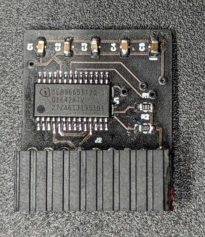
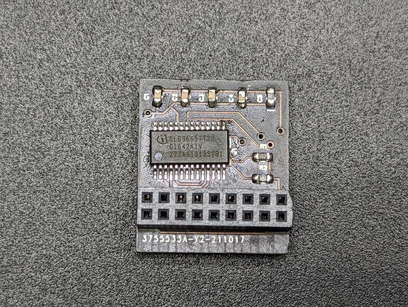
18-pin Module (TPM2-S/INFINEON)
The 18-pin module uses the following pinouts:
| DESC | DESC | ||
|---|---|---|---|
| F_CLKRUN# | ◯ | ◯ | GND |
| SERIRQ# | ◯ | ◯ | +3VSB |
| S_PWRDWN# | ◯ | ◯ | NC |
| GND | ◯ | ◯ | LAD0_L |
| LAD2_L | ◯ | ◯ | +3V |
| LAD1_L | ◯ | ◯ | LAD3_L |
| SMB_DATA_MAIN | ◯ | ◯ | TPM_RST# |
| SMB_CLK_MAIN | ◯ | ◯ | LFRAME#_L |
| GND | ◯ | ◯ | *CLK_33M_TPM |
Now this pinout is confusing. The SLB9665 only has 10 pins that match the pins in the above pinout configuration. Now this is awkward. Why do we have 4 additional pins that we have nowhere to hook up to? Took a little searching but this article was the gold mine for me in understanding that this 18-pin configuration was also used for TPM 1.2. The additional pins were simply a left over from the chips that support TPM 1.2. These are pretty modern boards so I'm not sure why ASRock decided to use the 18-pin configuration instead of the newer 14-pin configuration.
TPM 2.0 pinouts:
| DESC | DESC | ||
|---|---|---|---|
| F_CLKRUN# | ◯ | ◯ | GND |
| SERIRQ# | ◯ | ◯ | NC |
| NC | ◯ | ◯ | NC |
| GND | ◯ | ◯ | LAD0_L |
| LAD2_L | ◯ | ◯ | +3V |
| LAD1_L | ◯ | ◯ | LAD3_L |
| NC | ◯ | ◯ | TPM_RST# |
| NC | ◯ | ◯ | LFRAME#_L |
| GND | ◯ | ◯ | *CLK_33M_TPM |
Solve
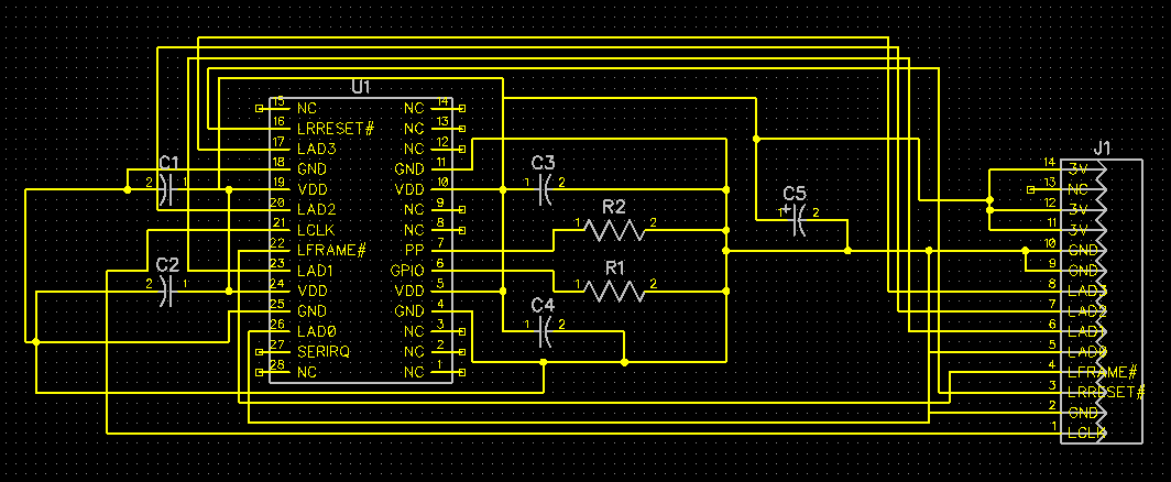
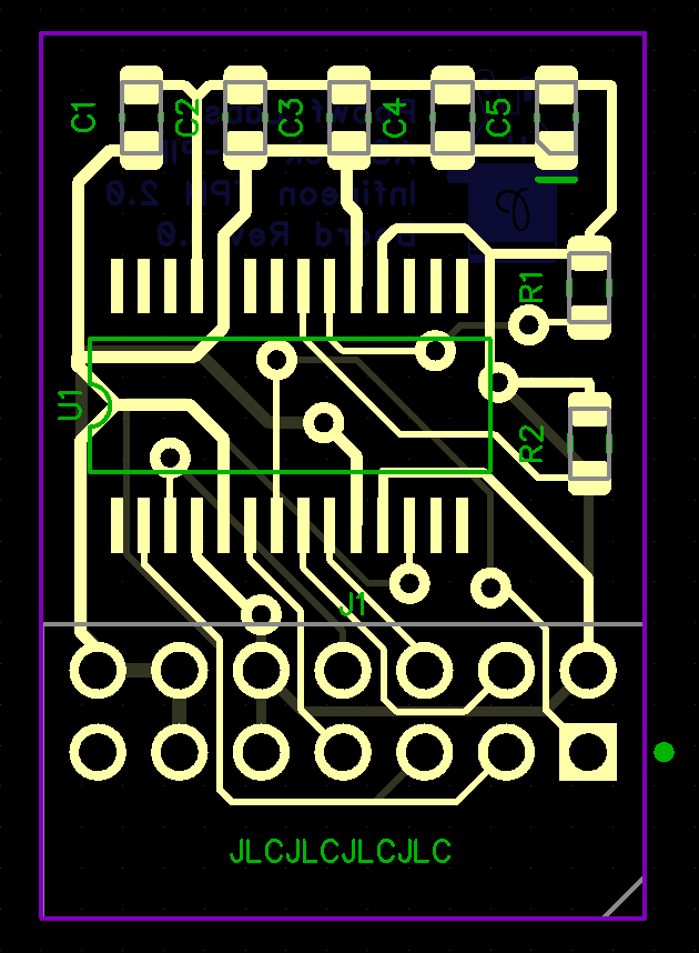
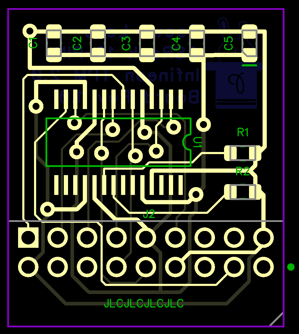
So now that I have my answers, I began designing the schematics per the datasheet and hooking them up for both the 14 and 18 pin configurations.
Components Required:
- PCB (Fabbed mine at JLCPCB)
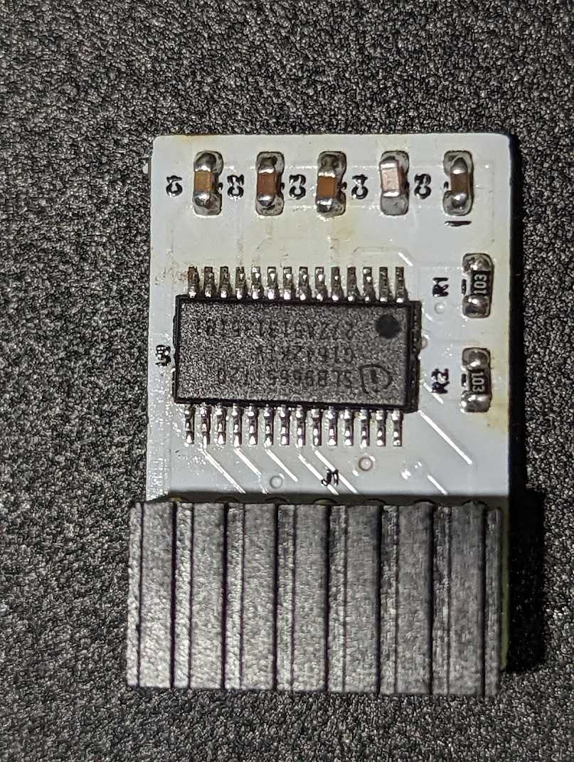
- Infineon
SLB9665TT20TPM Chip - 1 x 2x7 and 2x9 2.0mm pin header
- 5 x 100nF SMD capacitors
- 2 x 10K 0603 SMD resistor
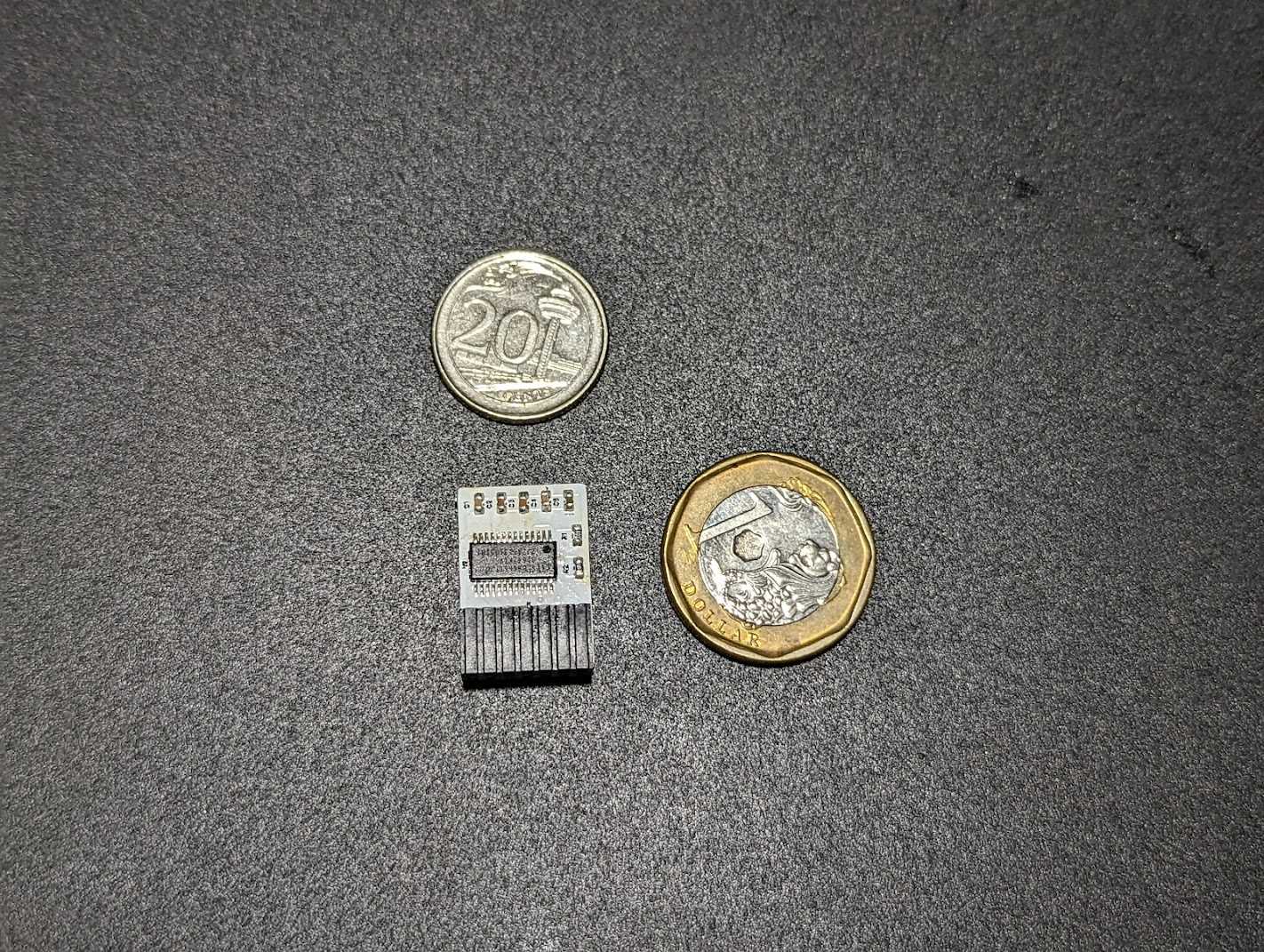
I had issues with finding the 2x9 pin headers, but they had 2x10 headers available, so I just bought that, snipped off 1 column of pins and sanded it down to get it smooth.
If you live in Singapore and want to try this out for yourself, I can ship you some boards of either variation as long as you pay for shipping or self collect.
If you're outside of Singapore, fabricating it yourself may be cheaper? But hey if you want to pay for shipping from Singapore, I'll oblige too.
I've included the gerber files in the repo:
https://github.com/zanechua/asrock-tpm
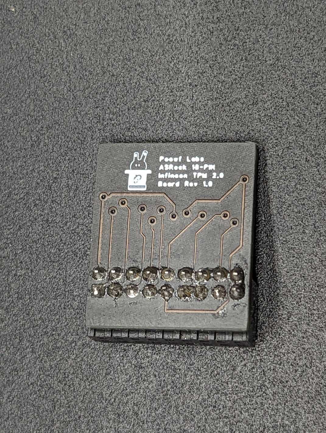
14-pin Module (TPM2-SLI)
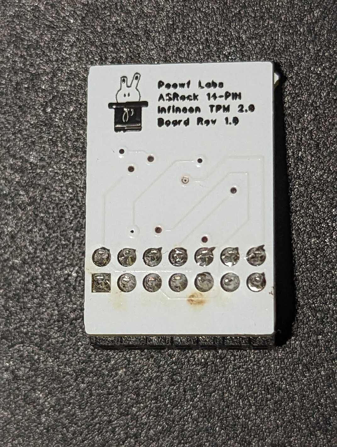
18-pin Module (TPM2-S/INFINEON)
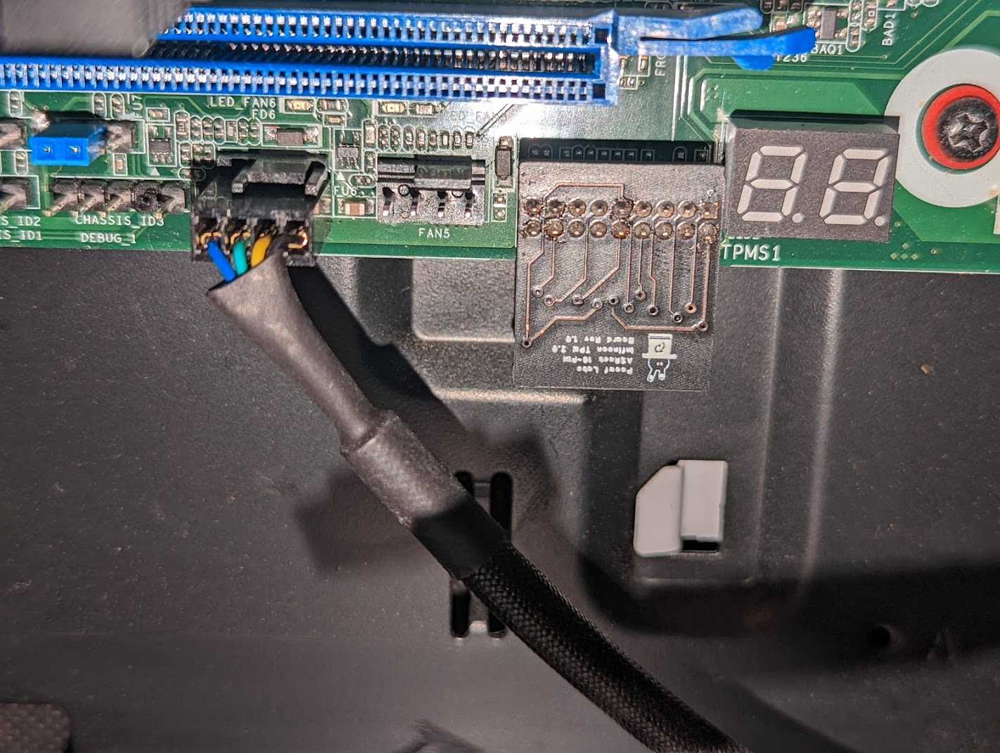
This post was delayed because of the 18-pin module as it was not working when I tested it. I only realized that ASRock had the pinouts reversed in their manuals and once I flipped the fabricated board over, it worked instantly. So now I can push this post up.
The other issue that I faced was that I needed to replace the pin headers with a right angle variant due to the GPU being above. My mistake turned out to be correct and the board is now facing downwards (exactly how I wanted it).


Upgrading TPM firmware
Depending on where you buy your TPM chips from, you may need to update the firmware on it. Use the following guides to upgrade the TPM firmware:
- Windows: https://silvenga.com/upgrading-firmware-infineon-tpm/
- Linux: https://qzhou.dev/updating-a-vulnerable-tpm
Firmware versions ending with '.2' seem to indicate an FIPS 140-2 compliant chip
References
- https://en.wikipedia.org/wiki/Low_Pin_Count
- https://www.asrockrack.com/general/productdetail.asp?Model=X570D4I-2T#TPM
- https://www.asrockrack.com/general/productdetail.asp?Model=X470D4U#TPM
- https://www.asrockrack.com/general/productdetail.asp?Model=ROMED8-2T#TPM
- https://serverfault.com/questions/927761/trusted-platform-module-tpm-versions-1-2-vs-2-0-and-header-number-of-pins
- https://linustechtips.com/topic/1363161-my-diy-asus-14-1-pin-tpm-m-r20-module/
- https://site.gothtech.co.uk/articles/gigabyte-motherboard-tpm-compatibity
- https://ottelo.jimdofree.com/tpm/
- https://www.infineon.com/dgdl/Infineon-data-sheet-SLB9665_2.0_Rev1.2-DS-v01_02-EN.pdf?fileId=5546d462689a790c016929d1d3054feb
- https://munetoh.hatenadiary.org/entry/20161020
- https://github.com/subutai-io/blockchain-router/issues/13
- https://superuser.com/questions/925097/do-tpm-modules-only-work-for-motherboards-of-the-same-vendor
- https://content.etilize.com/Manufacturer-Brochure/1026638573.pdf
- https://rog.asus.com/forum/showthread.php?96727-Asus-Infineon-TPM-firmware-update/page12#post84969
- https://silvenga.com/upgrading-firmware-infineon-tpm/
Comments
Ellerian Prince
03 April, 2022 at 10:04 AM
Solid stuff, mistakes are silver linings ;D
Dominic M. Luciano
06 April, 2022 at 2:04 PM
Thanks for this article; it was very helpful! I'm a professional engineering scientist and I've been eying the SLB9665 for a few weeks now as it may kill two birds with one stone for me regarding a project I'm working on. But I have some other questions about the TPM module slot on the motherboard in general that I haven't been able to find the info on, such as how much current can the +3VSB pin source, and the +3V3 pins source? I've been working on an aftermarket module with expanded features that would require a standby supply while the PC is off, and I don't want to run something like a DC barrel jack into the PC case from the outside to get constant power, so I've been considering using the +3VSB power in the TPM slot to power my module instead. But I'm looking for some more info on it.
Also, buying SLB9665 chips at the moment is damn near impossible. And samples are out of the question as I just get shuffled around trying to obtain a couple. Any chance you might know where to get a few SLB9665 in TSSOP?
I'd really love to chat more with you regarding TPM modules. I don't get on social media very much, but I'm on GitHub as @domiluci, and I can be found on Facebook under my full name. I'm also available by email. Hopefully we can find a way to get in touch! :)
Thank you very much for the article, and thanks in advance for any help you may be able to provide!
Arek
06 April, 2022 at 3:04 PM
There are 20 pin variants out there, too. Like
https://www.mercateo.co.uk/getpdf/CIEN8-20812453/CIEN8-20812453.pdf?viewOptions=secureMode
(including pinout which looks to be almost the same as 18 pin variant)
Zane
06 April, 2022 at 6:04 PM
@Dominic
I didn't include this this tidbit in the post because I figured it wasn't relevant, but when the module wasn't initially working, I did end up bridging the 3VSB+ to the 3V assuming that I did actually need to hook up 3VSB+. It turns out that when I did that and had slotted the module correctly (the second time), the motherboard refused to power on (Pressing the power button and nothing happens). Only when I removed the bridge, I was able to get the board to boot.
As for the SLB9665TT20 modules, I bought them off AliExpress. You should be able to find them quite easily. I paid about $2 per chip.
David N
07 August, 2022 at 10:08 AM
Hello Zanejchua,
i am contacting you through this section as i haven't found any other place where i could send you a message, i would like to talk with you about an Intel QL1K. I dont know much about servers because i am only a enthusiastic about home pc hardware.
Thank you, David
Zane
07 August, 2022 at 11:08 AM
Hey David N,
If you have either Twitter or LinkedIn, happy to have a conversation with you there.
David N
07 August, 2022 at 5:08 PM
I do have Twitter, it's @DavidNeagu5 but i can't message you, i think Twitter has the option where you can't Talk unless you both follow eachother(?).
Chasse
15 March, 2024 at 11:03 AM
Hi, I don't know much about the TPI interface but do know from its name it sounds like its serial. In the days of LPC - which not all boards support now the LPC interface could be used to show post codes, much like the post code monitor on your board. For some reason now some manufacturers are choosing to leave this feature out. Is there any way the SPI interface could handle this function and if it is doable could it also provide pass through for the existing add on TPM module?
Carlos
10 January, 2025 at 12:01 PM
Hello,
Would it be possible to adapt a 20-pin TPM 1.2 module to an Asrock motherboard with 18 pins?
Zane
20 January, 2025 at 5:01 AM
@Carlos
I think you should be able to. It depends on the pinout of the 20-pin.
I was working on a 20-pin variant for supermicro but didn't manage to get it working.